| Check out Part I or Part III of my Siggraph review. |
|
|
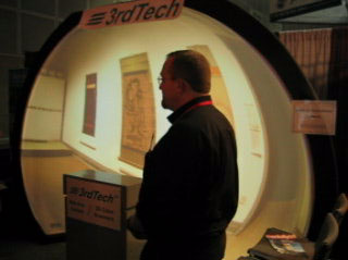
| This is almost pound for pound an idea I had in 8th grade. I even drew pictures in high school that match up with a rendering on screen creator elumens' page. I'm not saying my idea was all that amazing - it's just a domed screen and hemispherical projector, but I didn't think back then that I'd ever see it unless I built it. At $90k, it won't be coming home any time soon, but seeing it right there in front of me after having the idea so clearly in my mind for over a decade now was just awesome. |
|
|
The idea sprang from a wish to replicate in miniature the Tuttleman Omniverse Theatre's IMAX screen, which I loved as a kid at the Franklin Institute in Philadelphia. I've since learned that the majority of IMAX screens are simply 4 story rectangles, but the IMAX at the FI in PA was a dome that stretched beyond the extents of your vision (>180°), completely immersing you in the surround video, much like a planetarium, only with full quality film. You would sit in extreme stadium seating (45° floor that went up about 3 stories) with a projector in the center of all the seats, walled off from the seats around it. My version placed a 3-cushion couch at the center of the screen sphere, and was intended for the living room. Originally, I decided it would be built into one end of a room from plaster, and the projector would be just behind the couch, shining over the heads of the viewers. Later, I redesigned it to be made of stretchable screen (speakers behind it like at the IMAX) with loops sewn in the back that would link to the inside of interlocking bars that formed a partial geodesic dome, meaning you could pick up any time and move it somewhere else. I assumed to keep the triangulation simple, and limit the number of bars that had to be assembled, some sort of system would be created to help round out the screen, such as plastic braces that clipped to the dome's triangle bar assemblies to give more loop-hooking locations between the triangles, and the loops would have their lengths preconfigured. In later redesigns, I moved the projector to the floor in front of the couch, shining up at a more appropriate angle, and eliminating the need for staying out of the projector's path. I designed it's enclosure to double as a ramped footrest. All that was left was how to record video hemispherically. |
|
|
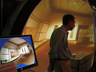
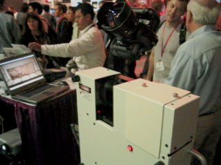
My best guess back in early high school, based on my limited knowledge of things like fisheye lenses, was that to record a hemisphere of information, you'd need a roughly hemispherical lens. To project it back out, same thing. I never really followed up on trying to figure that out, but at the show, I had a chance to look at the camera mounted on the 3D scanner that records the imagery. It had what appeared to be a nearly hemispherical lens :) Of course, this is way more advanced than anything I could've thought up back then. The lens is just the beginning. The screen is all well and good, and is part of elumens' projector package, but the software behind the display at the show was much more than the simple IMAX reproduction I was going for. This pic is of the DeltaSphere™ - 3000 3D scanner by 3rdTech. It captured the 3D room data on display in elumens' dome. To sum up, they were showing the absolute best realtime 3D CAD walkthrough I've ever seen. I asked the guy if I could pilot, and he taught me how to use their input device, and let me go to town. It was incredible, and so intuitive. There seemed to be no end to the detail in the room. The pad on the pedestal was just a small grip wheel on a little box with a cord running from it. The wheel could be turned clockwise and counter/anti clockwise to pan, tilted in all directions to tilt and roll the camera, pushed forward, backward, and to either side to truck in and out, and track left and right, and you could even pull up or push down on the wheel to crane the camera up and down! You could even mix up to 4 of these at once (fly up while tilting left, turning right, and moving forward!). After about 10 seconds, I was able to fly all through the house, banking into turns, flying up and over furniture, racing to a wall and stopping just in front of it to appreciate the detail. I took a little tour through hallways. You have to love well designed input devices. Now I want one for Maya! There was a slight lag in the framerate. I'd put it around 10fps, but it was amazing anyway, considering all that was going on. |

|
| One of the guys manning the 3dTech/elumens booth shows a girl how to pilot her way through the 3D scanned virtual world. |

|
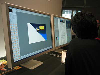
| I finally got a chance to come face to giant megapixel face with these 30" Cinema Displays that Apple has almost every one of my friends drooling over. These Apple guys didn't want to tell me anything about the monitors, or even get out of the way so I could look at them. That's how addictive having screens this large can be! You have to keep your wits about you. |
|
| I've had a lot of people up 'til now try to represent accurately to me through descriptions and gyrating gesticulations just how big these monitors really are, with horrible results. Nothing prepared me for how big they actually were when I saw them up close. Now that I've seen them, let me do my best to explain them to you. I'm a pretty big guy, but if the front of one of these monitors was a hole in the floor, I could easily dive through it. They're slightly larger than 1 unit, the name of which I've just determined will be called a "divehole." I wonder how long it'll be 'til Apple releases their 2 divehole displays! The monitor I'm typing on right now is about .63 diveholes. |

|
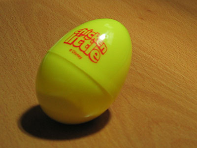
| In what will be remembered as the coolest thing they did in the first decade of this century, Disney Feature Animation was passing out Chicken Little eggs with Silly Putty™ in them! This is about as close as I got to actually bothering to watch any animations at this animation-heavy convention. The putty is yellow. I'm going to microwave it on low and see if it hatches. |

|
| I include this shot for sake of science. This was some display involving blended rear-projections, where 4 projectors would overlap. To anyone's unaided eye, this was a seemingly monochromatic, grey photo taken from an airplane. It was very bright, and had great tonal range. In my camera, however, even in the viewfinder, the 4 projections were quite obvious. I took a few shots, and they don't match up for color-shift. In one pic, for instance, of a different image, 3 of the squares appear to match up in color and intensity (yellowish), while the 4th (lower right) is more red. I imagine this could be anything from the screen material which may suffer from chromatic abberation (made obvious by the angles of the projectors), to it being a set of DLP projectors. The latter, perhaps my best guess, are color-wheel projectors that rapidly flicker images of each color channel's luminosity values through a rapidly spinning color wheel. Naturally, there's an associated frequency to this method which might fall outside the capture abilities of my camera...? |

|
| Sony Imageworks had a large area with artists sketching based on the instructions of a teacher at the front, working from an easel. The layout was very much like many art classes I took at college. |

|
| The folks at work tell me Sony does this every year, with the general concensus being that they just like showing off how artsy they are, or would have you believe. |

|
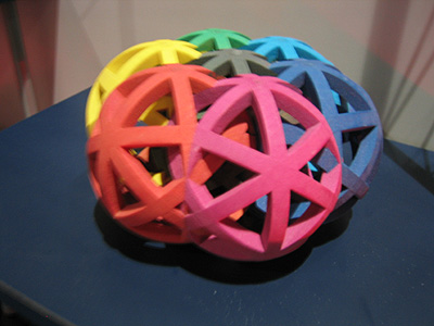
| This table of junk caught my eye, and I quickly realized these were examples of the first bit of rapid prototyping I ever heard about - the one that got me interested in the whole idea of CNC tooling. It's a laminate process that rolls out a sheet of glue-infused paper, heats it so it bonds to the layer below it, then laser etches out the cross section of your 3D model at that level, and cross-hatches out all the parts to be removed. After doing this for 3 hours per every inch (height) of model, you end up with a brick of plywood, which can be broken apart along all the cross hatchings, leaving behind a plywood 'carving' of your object. The result can be drilled, sanded, painted, cut, and even lacquered like real plywood. I read about this maybe 5 years ago, in Popular Science or equivalent tech magazine. I was so enamored by the process back then, that my feelings upon finding the booth verged on the kind you get when meeting one of your childhood tv heroes. I asked a few questions, but since I've been into this method for so long, I pretty much know all there is to know on the subject. |
|
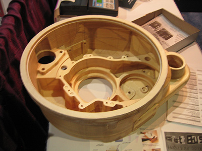
| Here's a much more complex machine part made with the layered paper rapid prototyping method. This had the lightish weight of basswood, and the texture of a thick layer of lacquer. It felt very solid, as though carved from a single block of wood. These folks also seem to be the ones who developed that "put your 3D face in a block of acrylic" process I'm starting to see in malls all over the place. I'm not sure if they invented it, though, or are just carrying on the faddish legacy. |
 Another crazy mocap girl (363kb MOV) |
| Ran into another mocap girl. What IS this crazy style of dancing? Where can one go to learn it? Does it tell stories, as the Hula? This exhibit was displaying what it touted as the fastest mocap software available. |
|
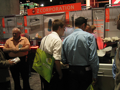
| Now we're talking! I ran into these Z-Corp guys about 4 months ago, and immediately fell in love with their line of 3D color printers. I even requested and received a free sample, which they had a larger version of at the show. I got to ask a few more questions, though most of them had already been answered by the friendly old man from a plant that uses one of these machines in their showroom, who called me to tell me the wonders of the product, and try to get me to lay down about $50k on their midrange model. You don't have to convince me. I want one! It's not about want, or even need. It's just about the $50k. If they can solve that problem, I'll take one as early as right now. |

|
| I talked to one of the guys for awhile and looked through many of the samples before realizing I was leaning on the actual machine. It hadn't even occurred to me the'd bring one, let alone both their low range and mid range models (low prints in one color, mid in full color, but not as large as the highend model). After all, the wood laminate guys didn't bring their machine, which granted is bulkier. My interest in their process wanes further... |
|
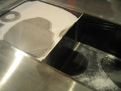
| There's the business end. Under the glass you see two bins, each with elevator floors. The left one lowers its floor, and you pack it with powder. The right one raises to be flush with the top of the bins. Then the powder bin raises ever so slightly, and the empty one's floor drops ever so slightly below flush, and a skim of powder is robotically raked from the one bin onto the other. Then a printhead on a plotter printer-like arm runs over the thin layer, spraying it with both color from actual inkject cartridges, and also a binding solution that makes it turn to something like plastic. It only does this in certain areas. Then the bins do their little movement again, another skim of powder is raked over the last one, which is hardening and changing color from the printhead. Again the printhead sprays a cross section of hardener and color onto the lowering bin, which fuses to the powder beneath it. Hours and hours later (overnight for the whole bin), a ton of cross sections have been hardened together and volumetrically colored. You have a full color, inside-and-out prototype part to work with. |

|
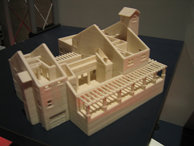
| Here are some parts the printers made. The top left accordion tube is a giant version of the sample one they sent me. It's been fed an infiltrant that turns it into a rubbery substance. You can squish and bend both versions. The others feel more like aerated plastic - lighter than typical molded plastic, as if you could bend hard and it would snap in a plastery way, but not glossy like plastic. In fact, there's a bit of a soft sandstone texture to the pieces, because of the way the powder joins together. |
|
| Though one of the cons that even the guy working the floor admitted to is the resolution being a bit low, since it's such an imprecise method (the chaotic falling of inkjet spray on chaotic sprinklings of starch powder), you get a good sense of just how intricate the designs can get with this method. The wood laminate would require a lot of picking with a needle pick to get all the pieces out from between the simulated rafters. |
|
| Another idea of the complex models capable. This would be difficult to impossible with typical milling devices. This particular piece was very heavy. There were a lot of things going on the middle. |
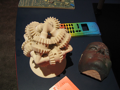 Gear Prototype (327kb MOV) |
| I saw this on the site months ago, and I've been dying to see if it was functional. It should be. Once you blow all the unhardened powder out, the wheels should spin freely. Here was my chance. I got some video of the gears actually working. |
| Tomorrow I'll post a bunch of things on all the haptic systems I ran into, and hopefully get the emergent technologies stuff up early Saturday. Of course there will be miscellaneous other things all throughout. |
| Check out Part I or Part III of my Siggraph review. |